This is my second post in a series on building a DIY Drop-on-Demand Inkjet Platform. In my first post, I broke out the components required for the platform. In this post, I’m building the first: An arbitrary waveform generator. This component produces the signal that drives the piezo (good detailed explanation here). When we’re working with a new material, we’ll tune the wave shape, frequency, and amplitude to produce well-formed drops.
The waveform generator needs to have these characteristics:
- Able to produce arbitrary waveforms. One of the purposes of this platform is to enable experimentation with different materials and inkjet devices. The ideal waveform may not be a simple sin or triangle wave.
- Maximum signal frequency of around 100kHz.
- Signal resolution of at least 8 samples per period at 100kHz.
- Voltage range: TBD. We’ll amplify this signal to a high voltage later. For now, let’s suppose the signal from the waveform generator needs to run a range of 0-5V.
- Must have precise timing control and be able to coordinate with other functions (eg. the trigger for the camera strobe that we’ll build in the next step).
- Must be built with easily available hardware that fits within the overall budget for the platform (which should total less than $1000 US).
The requirement for arbitrary waveforms and need to coordinate with other precisely timed operations means I’ll want to start by generating a signal with a microcontroller and converting to an analog signal with a DAC (digital to analog converter).
I’ll first discuss some naive approaches and why they don’t work.
An i2C DAC module: The MCP4725
The MCP4725 is a available as a breadboard-friendly module from Adafruit. An i2C driver is available. It’s very easy to get started. Here’s some trivial Arduino code to produce a triangle wave with the MCP4725 as fast as we can:
#include <Wire.h>
#include "Adafruit_MCP4725.h"

Adafruit_MCP4725 dac;
#define  SAMPLES   9
#define  CEILING   4095
uint16_t wave[SAMPLES];

void setup(void) {
  dac.begin(0x62);
  CreateTriangleWaveTable();
}

void loop(void) {
  for (int i=0; i<SAMPLES; i++) {
    dac.setVoltage(wave[i], false);
  }
}

void CreateTriangleWaveTable() {
  for(int i = 0; i < SAMPLES; i++) {
    int16_t v = (((1.0 / (SAMPLES - 1)) * (SAMPLES - 1 - i*2)) * CEILING);
    if (i > round(SAMPLES/2)) v*=-1;
      wave[i] = v;
    }
}
Here is the result from the oscilloscope:
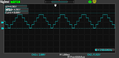
Frequency is only 300Hz? We’re limited by i2C speed. The default i2C clock speed is 100kbps. For each 12bit sample, we pay some i2C overhead to transmit an i2C address, a command and 16 data bits (even though the device has 12 bit resolution). We can increase i2C speed to “Full Speed”, 400kbps:
Wire.setClock(400000);
(Do this before Wire.beginTransmission() in Adafruit_MCP4725.cpp.)
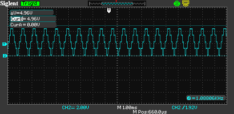
Unsurprisingly, that improved our speed by approx. 4X. Not good enough. The i2C protocol specifies a fast mode that is 3.4mbps, but it is not broadly supported. With an Arduino Due, I was only able to push the clock speed up to 2mbps before it became unstable:
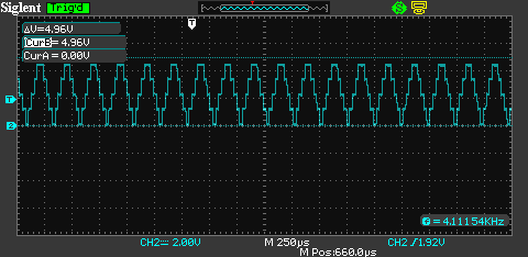
And still, just 4kHz. i2C isn’t going to cut it.
Arduino Due with onboard DAC
The Arduino Due has an onboard DAC. It’ll take a small change to the above code to use it:
#define SAMPLES 9
#define CEILING 4095
uint16_t wave[SAMPLES];

void setup(void) {
  analogWriteResolution(12);
  CreateTriangleWaveTable();
}

void loop(void) {
  for (int i=0; i<SAMPLES; i++) {
    analogWrite(DAC0, wave[i]);
  }
}

void CreateTriangleWaveTable() {
  for(int i = 0; i < SAMPLES; i++) {
    int16_t v = (((1.0 / (SAMPLES - 1)) * (SAMPLES - 1 - i*2)) * CEILING);
    if (i > round(SAMPLES/2)) v*=-1;
    wave[i] = v;
  }
}
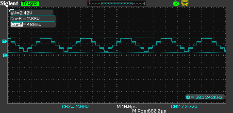
30kHz. Getting closer. The voltage range is now ~400mV to 2.88mV. The Due is a 3.3V device. The default analog reference voltage is 3.3V. The Due’s DAC output range goes from 1/6 to 5/6 of the AREF value, rather than rail-to-rail. Interesting and possibly annoying. We’ll do something about this later.
I still want to get up to 100kHz and also… I’m not satisfied with the resolution of these waveforms. But if I double the resolution (number of samples in a period), it will cut the frequency in half.
Arduino Due with onboard DAC and Direct Memory Addressing
In my naive examples so far, I’ve just output values as fast as I can in the main loop. If I want to control other capabilities with this microcontroller, it will interfere with the waveform output. Also, the operations required to look up a value in the wave table and perform analogWrite are too slow. We want a solution that uses timer interrupts to free up the main loop and enables faster (perhaps buffered) access to the wave table to improve speed.
The Arduino Due is built on the Atmel SAM3X8E Cortex M3, which has an onboard Direct Memory Access (DMA) controller. We’ll use this to buffer our waveform samples onto a hardware register so we can read them very quickly when needed. We’ll also set up the DAC to be triggered by a timer interrupt.
#define  SAMPLES   9
#define  CEILING   4095
uint16_t wave[SAMPLES];

// Incantations for DAC set-up for analogue wave using DMA and timer interrupt.
// http://asf.atmel.com/docs/latest/sam3a/html/group__sam__drivers__dacc__group.html
void setupDAC() {
  pmc_enable_periph_clk (DACC_INTERFACE_ID) ;   // Start clocking DAC.
  dacc_reset(DACC);
  dacc_set_transfer_mode(DACC, 0);
  dacc_set_power_save(DACC, 0, 1);              // sleep = 0, fast wakeup = 1
  dacc_set_analog_control(DACC, DACC_ACR_IBCTLCH0(0x02) | DACC_ACR_IBCTLCH1(0x02) | DACC_ACR_IBCTLDACCORE(0x01));
  dacc_set_trigger(DACC, 1);
  dacc_set_channel_selection(DACC, 0);
  dacc_enable_channel(DACC, 0);
  NVIC_DisableIRQ(DACC_IRQn);
  NVIC_ClearPendingIRQ(DACC_IRQn);
  NVIC_EnableIRQ(DACC_IRQn);
  dacc_enable_interrupt(DACC, DACC_IER_ENDTX);
  DACC->DACC_PTCR = 0x00000100;
}

void DACC_Handler(void) {
  DACC->DACC_TNPR = (uint32_t) wave;
  DACC->DACC_TNCR = SAMPLES;                // Number of counts until Handler re-triggered
}

// System timer clock set-up for DAC wave.
void setupTC (float freq_hz) {
  int steps = (420000000UL / freq_hz) / (10*SAMPLES);
  pmc_enable_periph_clk(TC_INTERFACE_ID);
  TcChannel * t = &(TC0->TC_CHANNEL)[0];
  t->TC_CCR = TC_CCR_CLKDIS;                // Disable TC clock.
  t->TC_IDR = 0xFFFFFFFF;
  t->TC_SR;                                 // Clear status register.
  t->TC_CMR =                               // Capture mode.
              TC_CMR_TCCLKS_TIMER_CLOCK1 |  // Set the timer clock to TCLK1 (MCK/2 = 84MHz/2 = 48MHz).
              TC_CMR_WAVE |                 // Waveform mode.
              TC_CMR_WAVSEL_UP_RC;          // Count up with automatic trigger on RC compare.
  t->TC_RC = steps;                         // Frequency.
  t->TC_RA = steps /2;                      // Duty cycle (btwn 1 and RC).
  t->TC_CMR = (t->TC_CMR & 0xFFF0FFFF) |
              TC_CMR_ACPA_CLEAR |           // Clear TIOA on counter match with RA0.
              TC_CMR_ACPC_SET;              // Set TIOA on counter match with RC0.
  t->TC_CCR = TC_CCR_CLKEN | TC_CCR_SWTRG;  // Enables the clock if CLKDIS is not 1.
}

void setup() {
  analogWriteResolution(12);
  CreateTriangleWaveTable();

  setupDAC();
  float freq_hz = 200000; // Target: 200kHz
  setupTC(freq_hz);
  NVIC_EnableIRQ(DACC_IRQn);
}

void loop() {}

void CreateTriangleWaveTable() {
  for(int i = 0; i < SAMPLES; i++) { int16_t v = (((1.0 / (SAMPLES - 1)) * (SAMPLES - 1 - i*2)) * CEILING); if (i > round(SAMPLES/2)) v*=-1;
    wave[i] = v;
  }
}
Note that I’ve configured to target 200kHz. Here’s the view from the scope:
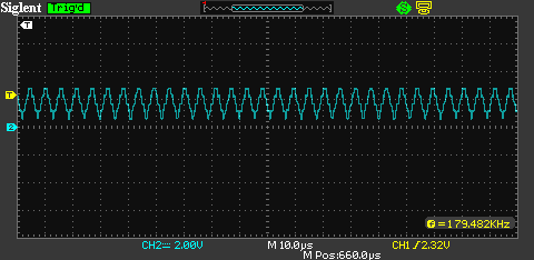
Actual frequency is 180kHz (That appears to be the max for any target). So this works. Now I want to address the voltage range issue. I’m adding a pair of LMV358 op amps configured for 10X gain. I’ll reduce the CEILING in the above code, so the amplitude of our wave from the DAC is 0.5V.
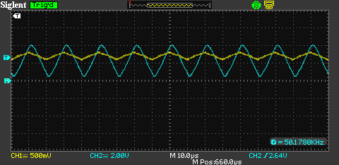
Also, for the image above, I reduced the target frequency to 50kHz and increased the resolution to 31 samples for a smoother wave.
Looking good. Finally, Let’s prove that we can produce arbitrary waveforms. Here is a house with a chimney at 50kHz:

That’s it. The code above is the basis for an Adruino Due-powered arbitrary waveform generator that meets the stated requirements. Next up, a camera and lighting rig to capture drop formation in microsecond time.
Thank you very much for this article. I love the stuff that you are doing. We are working on Open Source Hardware. Could you imagine using it for your project? Details at https://pslab.io What do you think?