This is my 3rd post in a series on building a DIY Drop-on-Demand Inkjet Platform. In this post, I am building a camera and lighting rig for capturing moments in the drop formation and jetting sequence.
Requirements:
- The nozzle orifice of a piezo inkjet may be 10s to 100s of microns. While drop diameter will be larger than the orifice, to capture as much information as possible, the lowerbound for our zoom should enable us to capture 10s of microns.
- The full jetting sequence for a drop may take 10s of microseconds, so the rig needs to capture moments within that sequence, without significant motion blur.
- Cost and accessibility: Components should be generally available and accessible to hobbyists. Costs should fit within our overall budget of $1000 for the whole platform.
- Ideally, the camera and lighting setup should be small and simple enough to operate in the environment where the piezo inkjet is used (eg. mount on the gantry of a 3d printer or microfluid dispenser).
General approach: Long exposure w/ fast strobe
The first thing we need to determine is how to capture an event that takes place within a few microseconds. While I’m sure a high-speed camera could tackle this task, it would break the budget. Instead, I’m opting for a high-speed flash. Imagine you want to capture the moment a balloon pops. A common technique is:
- Set up a camera in a dark room.
- Configure for a long exposure.
- Connect the flash to a sound trigger.
- Start exposing.
- Pop the balloon.
The image sensor captures nothing while the room is dark. When the balloon pops and the flash triggers, the scene is lit for a brief moment, and just that moment is captured by the sensor.

This is the inspiration for the technique I’m going to use. I’ll need the following:
- A webcam with configurable exposure (a lot of webcams have auto-exposure that can’t be overridden).
- A zoom lens capable of capturing drop formations.
- A light source to act as the flash (or strobe).
- A trigger to manage the duration and delay of the strobe, relative to the waveform driving the piezo.
- A “lightbox” to keep out external light and control how light from the strobe interacts with the subject.
Camera Selection
I chose the Korukesu C1 USB Camera, because I’ve used it for a number of computer vision projects. It has a CS mount to support different lenses. It is highly configurable in Linux using v4l2. It’s compact and quite inexpensive (around $100).
Lens #1: CS Mount Microscope Lens
I experimented with a few zoom lenses, but quickly discovered that I will need a microscope lens. I fist tried this style of CS mount microscope lens:
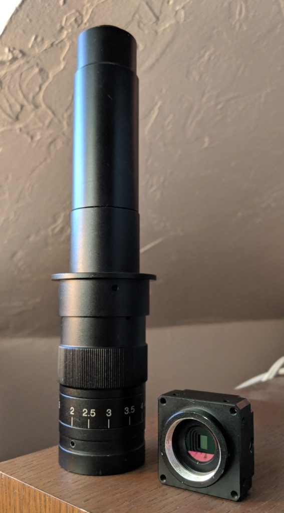
This lens could capture images in the zoom range I want, but … I hated it: The lens itself is huge, about 12″ long (dwarfs the tiny Korukesu C1). Worse, the minimum object distance was somewhere around 5 or 6 inches, so I had to position it far away from the piezo and lightbox. I also found that the zoom and focus controls are difficult — hard to dial in. With this unwieldy thing on my desk, I couldn’t bump it or I’d have to spend minutes refocusing.
Lens #2: Hacking up a Cheap USB Children’s Microscope
While researching CS-mount microscope lenses, I kept bumping into these cheap USB microscopes.
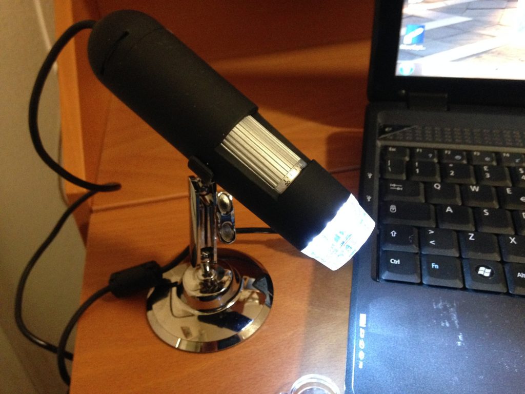
Some of these went as low as $15. $20 with slightly dubious 1000X zoom on Amazon Prime. Dubious because the advertised magnification includes display of a 1024X768 pixel image on a 21 inch monitor. But for $20, it’s worth a shot.
The model I purchased is branded “Jiusion”, but the same model appears to be available with many different names. When I unboxed the microscope and tried it out, I was kind of impressed, except for a couple of issues:
1) Any small amount of stress on the base of the cable would cause dropped frames or connection loss. Super annoying. Maybe fixable if I add stress relief at the base.
2) The camera was only capable of capturing 1024X768 images.
3) Exposure was controlled automatically and could not be overridden (at least with device drivers I had access to). Possible deal breaker.
The lens in this microscope can’t be anything fancy, but when it works, the images are promising. What if I break it open, gut the lens, and make a mount for my Korukesu C1 camera? I found this handy YouTube video that explained how to disassemble the microscope without breaking the good parts.
The lens was mounted on a pair of guide rods, inside a threaded tube. When you rotate the tube, the lens fixture slides closer or farther from the image sensor, on the guide rods. This is how zoom is controlled on the microscope. Neat.
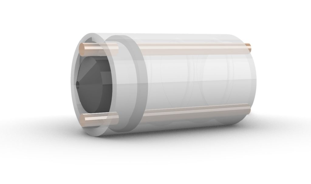
On the microscope, the guide rods are soldered to the main PCB (where the image sensor is) at the base end. I made a 3D-printable “cap” for the tip end to secure the rods instead. I made new rods from a clothes hanger and pounded them into place with a hammer.
Now, when I rotate the cap, the lens fixture slides closer / farther to the image sensor. This will be my “zoom” control.
Lightbox
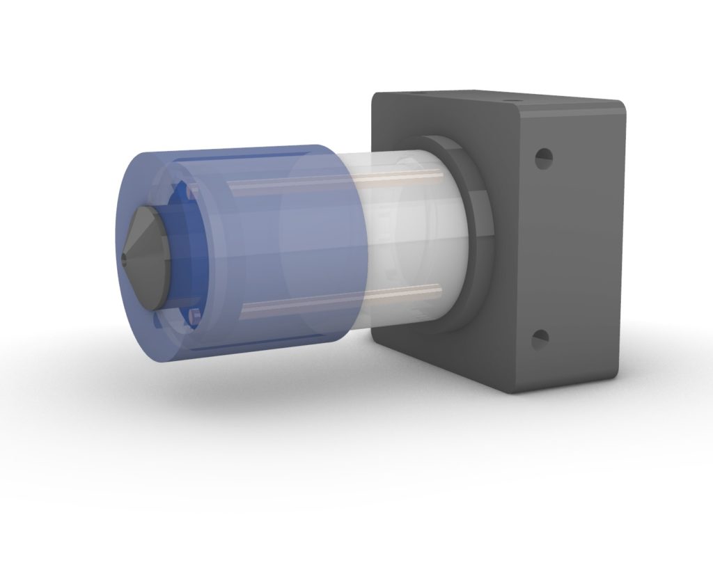
Now I need a place to securely mount the piezo tube, the camera, and a light source. I also need to keep out any outside light, so that the camera’s image sensor isn’t getting any light until the moment when the strobe is engaged. I designed and 3D printed this small lightbox.
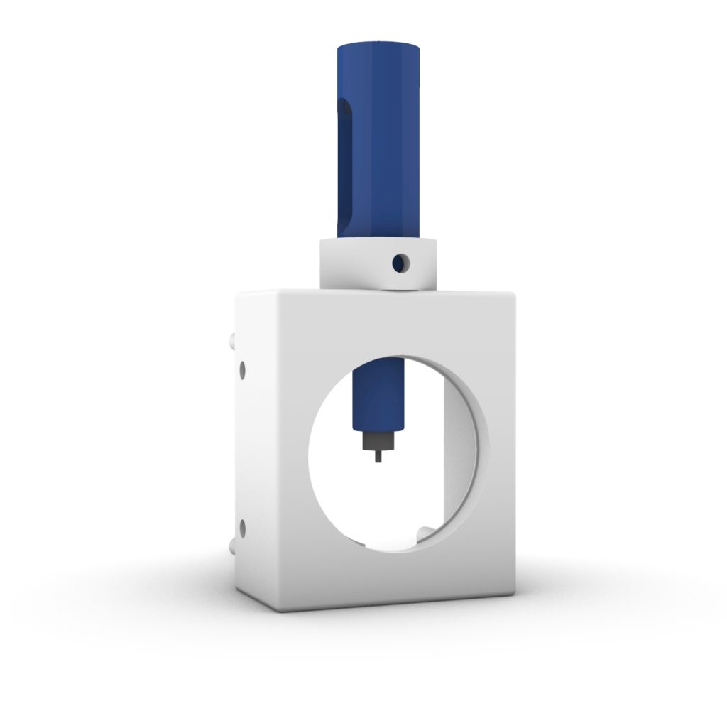
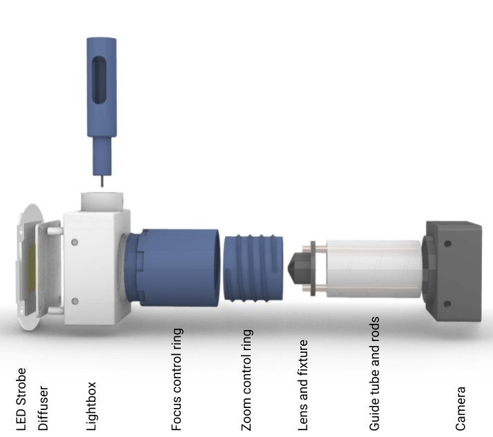
The light source will mounted to the back. The piezo tube is housed in a 3D-printed jacket (blue in this rendering) and inserted through the top. The camera has a view through the circular window in the front. I designed a focus ring that controls the distance form the lens to the piezo nozzle (the focal object), and attaches to the front of the lightbox. Here is how everything fits together:
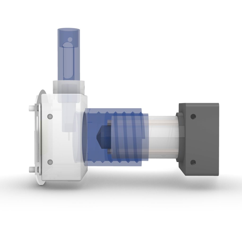
I rotate the outer ring to control object distance (“focus”). I rotate the inner ring to control the distance from the lens to the sensor (“zoom”). It is a little awkward if I really want to control both of these, but I’ve found I keep the zoom fixed and only modify the focus.
Strobe: 50W constant current landscape spotlight LED
Image exposure is a function of the amount of light (we might call this “brightness”) the sensor is exposed to and the amount of time of the exposure. We’re trying to capture an event that takes place in a few microseconds, so we want to strobe our light source for only a few microseconds. We can make up for the short duration of the strobe by increasing the brightness of the light source.
I first tried a 12V LED array. I was able to get some results that might be acceptable, particularly if I post-process the image to improve contrast:
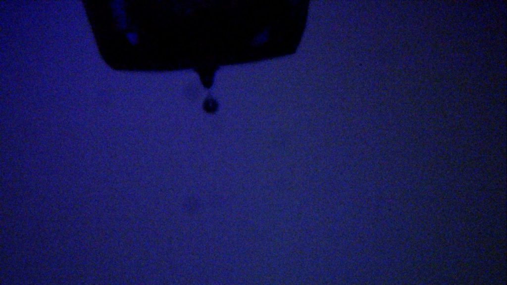
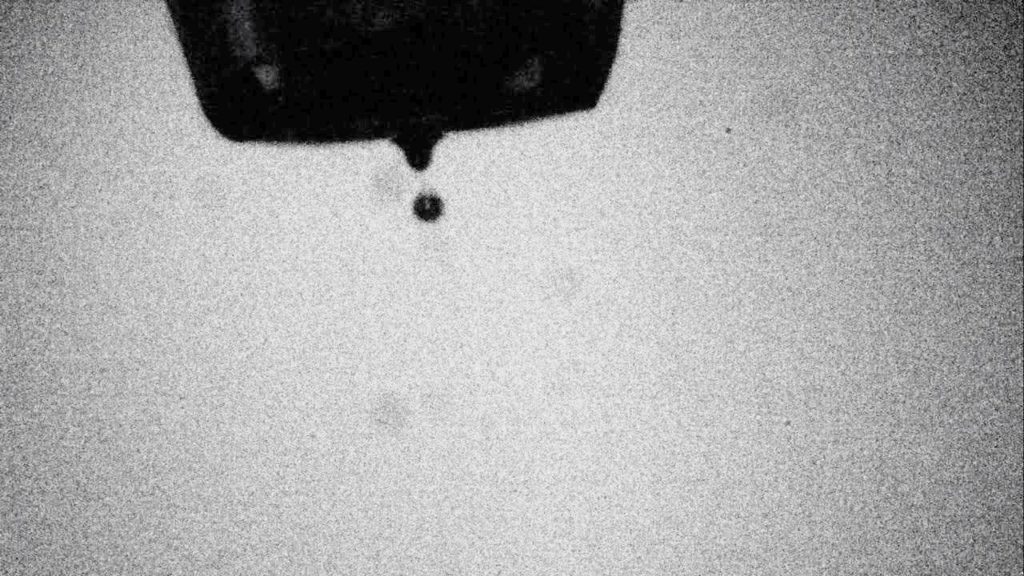
But I had some consistency issues and experienced motion blur when I increased the strobe duration to 20+ microseconds.
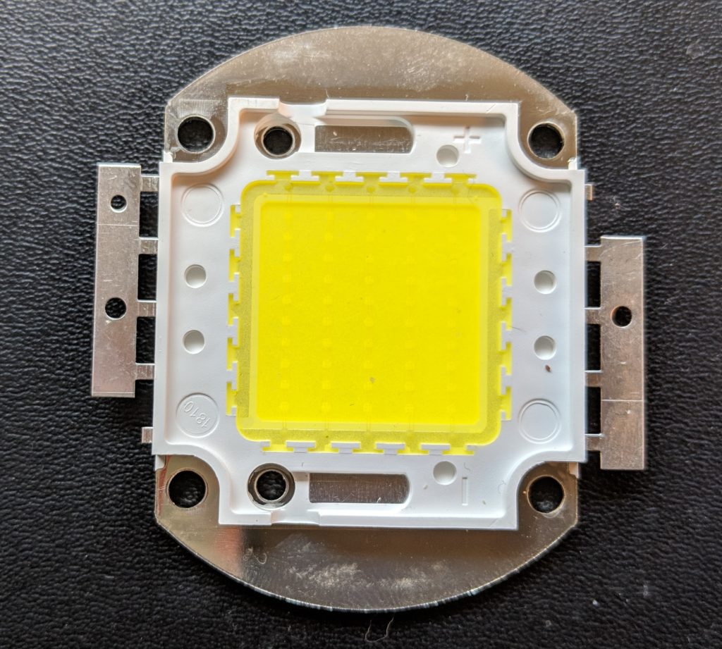
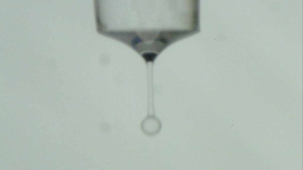
I tried a few alternatives before landing on this solution. This is an incredibly bright LED array, intended for use in landscape spotlights. It operates at ~30V and 1.5Amps. It requires a constant current driver. Here is a sample image with this light source strobed for 2 microseconds:
I also had to diffuse the light. I printed a simple 0.6mm diffuser in white PLA.
High speed switching
Finally, I need to create a switch to strobe the LED. The LED operates at 30+V and 1.5Amps. I want to control the strobe duration, down to 1 microsecond. Since the supply voltage is significantly higher than logic voltage, the options I considered were relays and MOSFETs.
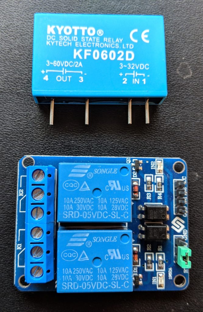
I experimented with mechanical and solid state DC relays and found that as I approached 1 microsecond strobe durations (attempting to enable supply voltage to the LED for 1 microsecond), the relays failed to switch.
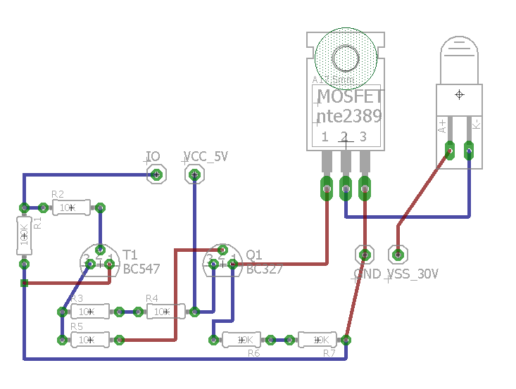
Next, I tried an N Channel MOSFET, configured as a high side switch. The current flow from the Arduino’s GPIO wasn’t sufficient, so I made a PNP transistor circuit as a “pre-switch” so that the source for the MOSFET was the 5V supply VCC for the Arduino.
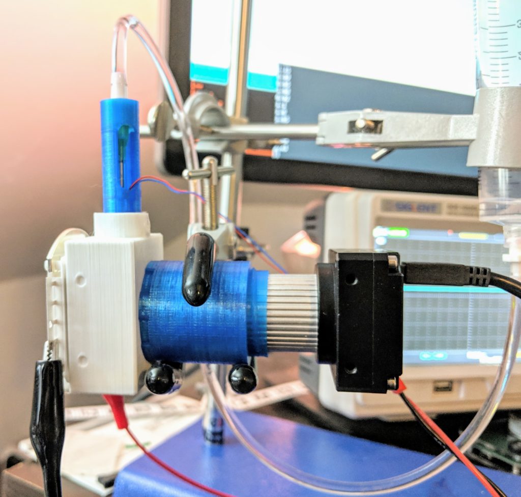
 Final assembly
Here’s how everything comes together:
Final parts list for lighting rig
- Korukesu C1 camera
- “Jiusion” 1000X microscope
- 3D printed zoom and focus rings
- A clothes hanger? Or other source of 2mm 3″ rods.
- 3D printed lightbox
- 3D printed diffuser
- 50W LED array
- Constant current driver
- Switch circuit
- N Channel MOSFET (NTE 2389)
- BCN547 NPN transistor
- BCN327 PNP transistor
- 1 100Kohm resistor
- 6 10Kohm resistors
The switch is driven by the Arduino Due used in Part 2: Arbitrary Waveform Generator. I’ll discuss the software in more detail in another post.
An interesting technique you could also consider would be to use three LEDs (red, green, blue) as closely-timed strobes. You could then convert each color channel of the resulting image to individual greyscale captures, allowing three shots to be taken with each exposure. Idea via doi 10.1006/jcis.2002.8225