Background
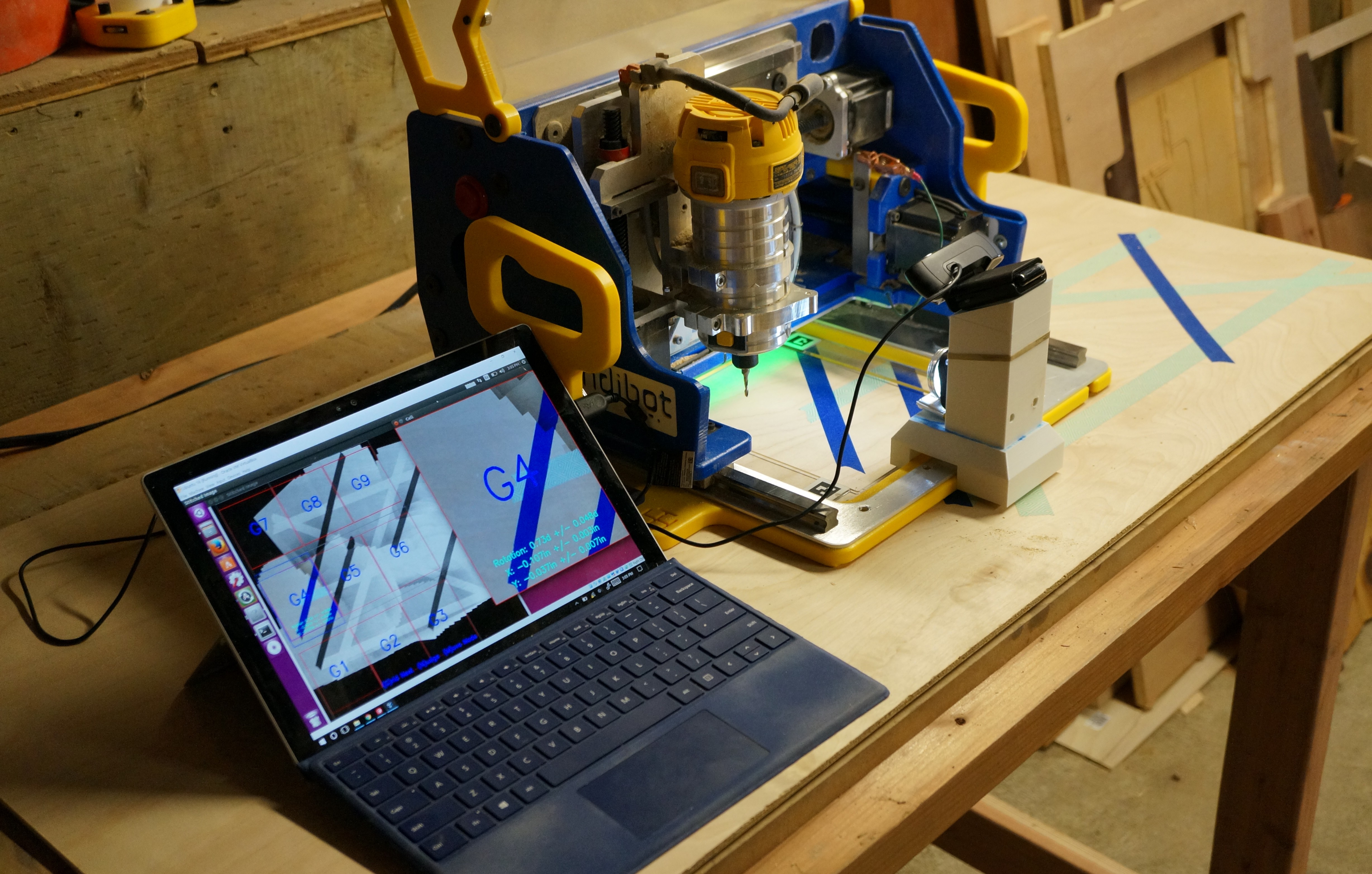
I use a Handibot for CNC woodwork. If you aren’t familiar, Handibot is a portable CNC router that you place on top of your workpiece to make pre-programmed cuts. It can cut the same designs and perform most of the same tasks as a full sized CNC machine, but compared to full-size CNC machines, it’s compact — small enough to pick up and move around. Since the machine sits on top of a workpiece, the size of project it can tackle is virtually unlimited. The downside of the compact design is that it only cuts 6″x8″ at one time before the operator must physically lift and reposition the machine for the next “tile” of a cut. So for a large project on a 4’x8’ sheet, you may reposition and register the Handibot 96 times.
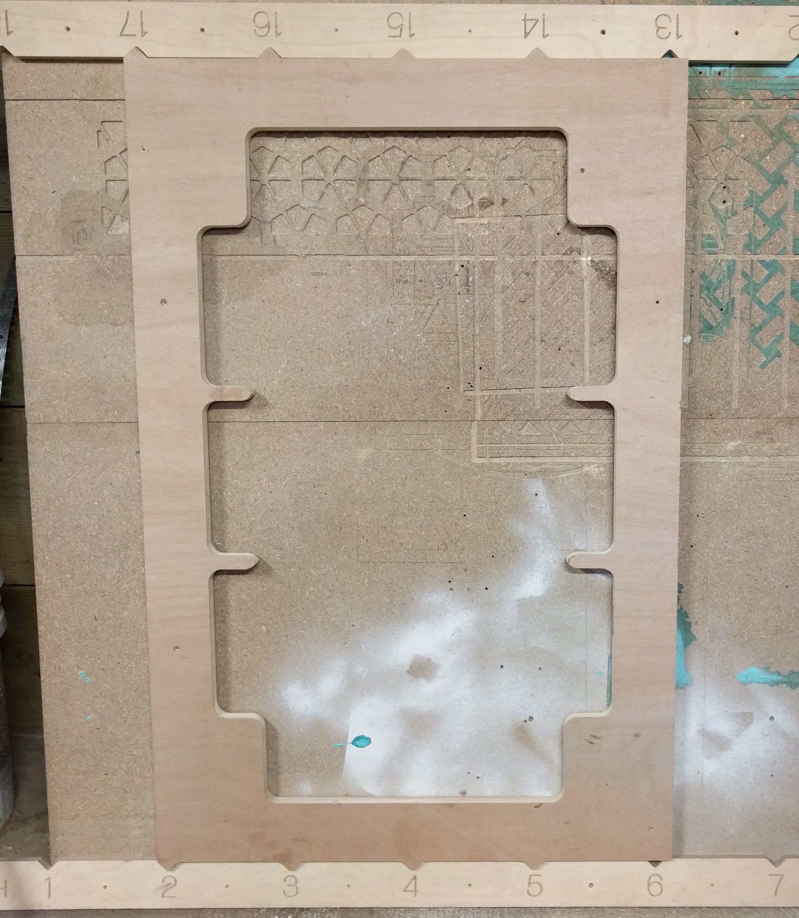
Today, when I’m performing multi-part cuts, I use a custom rigid jig to register the position for each cut. These jigs aren’t bad, but they require building a new tool, possibly with access to different machinery, need additional workspace, and physically limit the size of my projects.
Idea: Optical Registration
I’m going to try an experiment. Can I improve my experience with the Handibot by performing multi-part cuts using computer vision for registration? In short, can I use computer vision to capture a full view of my workpiece (ie: “scan” the workpiece), then identify the target and current position of the machine on the work surface, for each cut, with high precision (+/- 0.01”)? And will precise computer vision-based registration make for a better user experience?
Full disclosure: I chose this project as an opportunity to learn about computer vision and get experience with OpenCV. My goal was not to compare and find an ideal registration method, so I did not consider alternatives. That said, I don’t believe my precision requirements could be met with alternatives including LIDAR, light-based proximity sensors (eg. the popular Sharp proximity sensors), or ultrasonic sensors. If you disagree, and can point me to a good alternative to a camera-based solution, please let me know.
Summarizing Findings
You can use and modify Handicam yourself, and I’ll provide more details on GitHub. For this post, I’m jumping straight to findings.
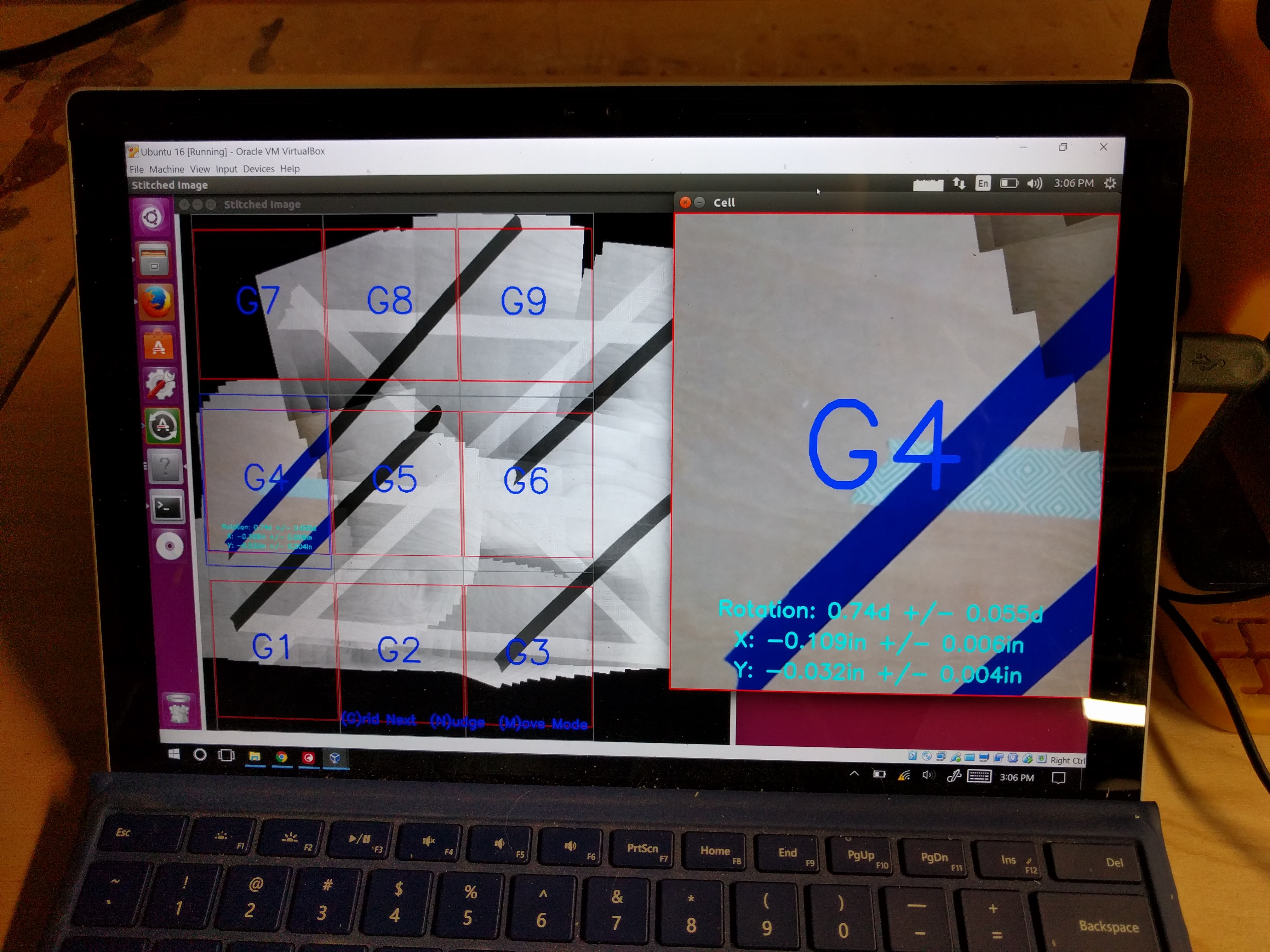
Good news: We can create an optical registration solution for the Handibot with better than 1/100” precision. Doing so requires some custom parts, including a camera mount and Aruco marker board. It also requires a good camera with control over focus and exposure and reasonably good lighting. The code on GitHub is available as a proof of concept.
Now the bad news: Using Handicam requires manually placing the machine for each tile. Accurately maneuvering the Handibot, which weighs about 50lbs and has an anti-skid rubber bottom, is difficult and cumbersome. So, for example, while Handicam can provide feedback that the Handibot needs to be moved 1/32” on the X-axis, lifting and moving the machine that distance by hand, within a tolerance of 1/100”, takes a lot of frustrating trial and error. In my experience, I could do it, but it took minutes to adjust the position for each tile.
With access to Handicam, I still prefer a rigid jig. A jig gives me reasonable precision and significantly less effort per tile. That said, there are some future work areas that could greatly improve the solution and make it viable:
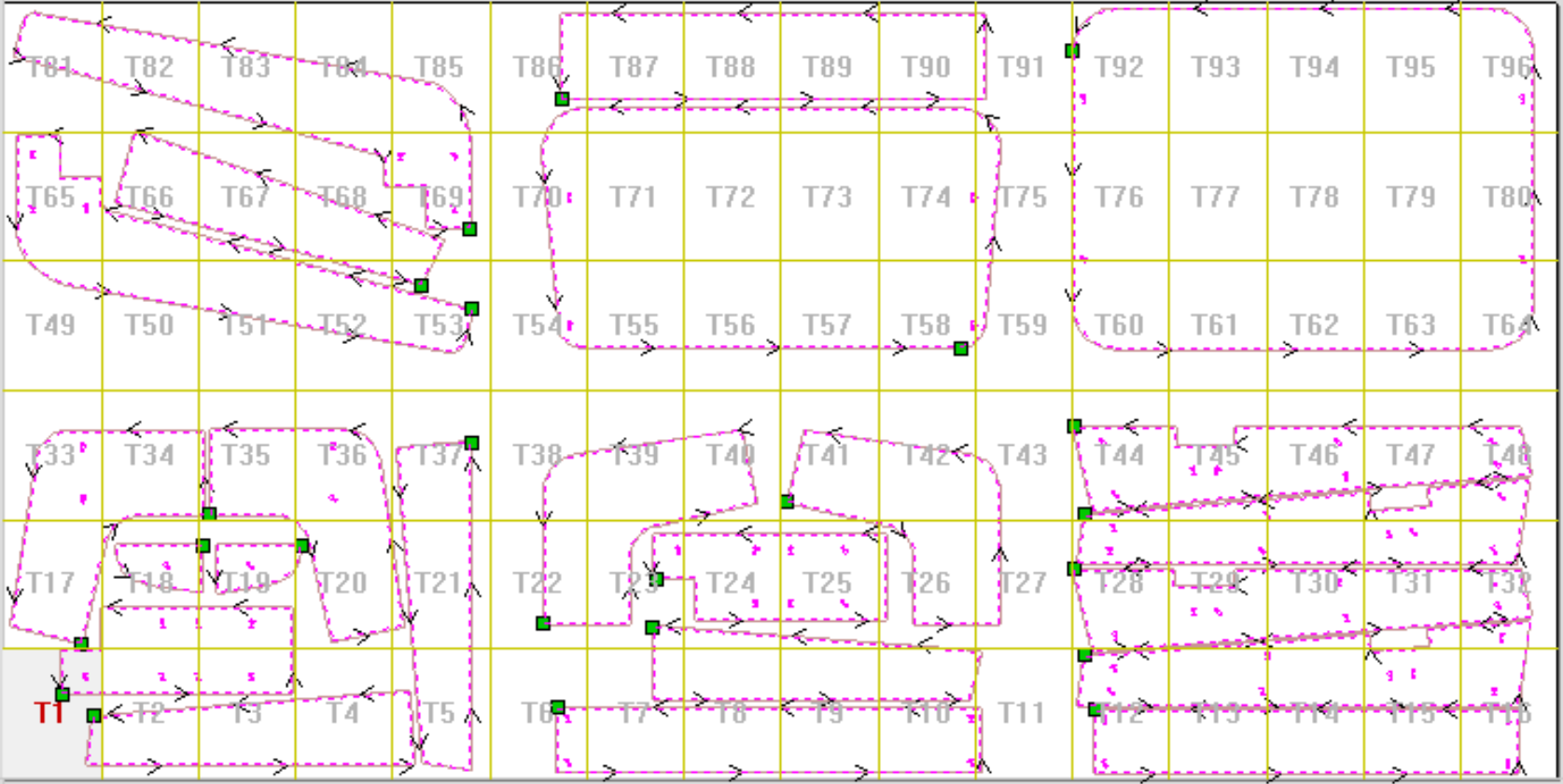
On demand single-tile CAM, based on the Handibot’s current position: Rather than pre-program a grid of “tiles” for a complete multi-part cut then force the user to accurately position the machine for each tile, generate the cut instructions for any position that the user places the machine, on demand. This way, the user can roughly move the machine to where a cut is needed, without fussing about accurate placement, but still get a precisely aligned cut according to the machine’s measured position on the workpiece.
Autonomous movement for the Handibot: Turn the Handibot into a mobile robot, using wheels, tracks, or belts for accurate repositioning. Since I started work on Handicam, I’ve learned about some new options for CNC routing with autonomous motion. Considering these new options, I think that the Handibot and its tile-based approach for large cuts may still offer some advantages: The weight and anti-skid features that make for tedious manual repositioning between cuts are actually a virtue at cut time, because they ensure the machine stays precisely aligned in spite of large forces on the router that could move the whole machine. Further, the tile-at-a-time approach enables the user to choose to add additional work-holding when needed.
I don’t currently have any concrete plans to pursue these ideas, but if I a tinker more, I’ll try to share. Thanks!